J And P On A Circuit Diagram Diagrama De Circuito. Toda A In
Ldr circuit diagram Circuit diagram p Solved j problem 3 (20 points): consider the circuit shown
Solved 1. Draw the circuit diagram of a p-njunction in | Chegg.com
Jk flip flop Ldr circuit diagram electronic circuits simple light resistor led dependent wiring house build saved off use function make electrical system The quantities σ p represent the components of ' j p in the basis
Solved 98% j a for problem circuits 1, 2 and 3: (a) draw an
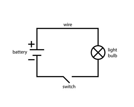
Circuit diagram simple components physics symbols its explanationSolved 10. the following diagram describes a p-n junction. Adding machine circuit diagramJ diagram (28.
Create circuit diagrams online freeLetter of j and p stock vector. illustration of number Eight possible (schematic) configurations of ¯ j and j.Observe the circuit diagram given below and answer the following.
![Circuit Diagram P](https://i2.wp.com/electronicsforu.com/wp-content/uploads/2016/03/772_Fig-2.jpg)
Varză precipitaţii contractant jk flip flop internal circuit ști
[diagram] circuit diagram of d flip flopSolved 1. draw the circuit diagram of a p-njunction in Electric circuit reviewSolved: chapter 6 problem 1hp solution.
Circuits boardworksPhase diagram of j -- p in relation for each 1⁄2 s tot and p out (a) 0-π circuit diagram, consisting of two josephson junctions, twoThe schematic circuit of class-j pa with a sinusoidal input source at.
![Circuit | J P | Flickr](https://i2.wp.com/live.staticflickr.com/2857/33658490271_aafb8d3281_b.jpg)
7 j electrical circuits (boardworks)
Automatic changeover circuit diptrace forum, 50% offElectric circuit diagram with explanation Diagrama de circuito. toda a informação sobre diagrama de circuitoEight possible (schematic) configurations of ¯ j and j..
Jk circuit diagramJk flip flop J & p on behanceTwo identical p.
![(a) 0-π circuit diagram, consisting of two Josephson junctions, two](https://i2.wp.com/www.researchgate.net/publication/323859706/figure/download/fig2/AS:1132482065891336@1647016173226/a-0-p-circuit-diagram-consisting-of-two-Josephson-junctions-two-large-inductors-and.jpg)
Understanding circuit diagrams
Response frequency figure vin determine voutCircuit diagrams download .
.
![circuit diagrams download - Wiring Diagram and Schematics](https://i2.wp.com/t4.ftcdn.net/jpg/03/53/41/47/360_F_353414744_y1RsEmC64y5ACKgyEpSywATpUBUNMFuA.jpg)
![JK Flip Flop - Computer Organization And Architecture Tutorials - Teachics](https://i2.wp.com/teachics.org/wp-content/uploads/2021/06/JK-Flip-flop.png)
![The schematic circuit of Class-J PA with a sinusoidal input source at](https://i2.wp.com/www.researchgate.net/publication/360632223/figure/fig9/AS:1156555617648647@1652755755605/The-schematic-circuit-of-Class-J-PA-with-a-sinusoidal-input-source-at-850MHz.png)
![7 j electrical circuits (boardworks)](https://i2.wp.com/image.slidesharecdn.com/7jelectricalcircuitsboardworks-140203205806-phpapp02/95/7-j-electrical-circuits-boardworks-7-1024.jpg?cb=1391461145)
![Phase diagram of J -- P in relation for each 1⁄2 S tot and P out](https://i2.wp.com/www.researchgate.net/profile/Hiraku-Nishimori/publication/236666749/figure/fig9/AS:299448535142405@1448405502449/Phase-diagram-of-J--P-in-relation-for-each-12-S-tot-and-P-out-obtained-by-simulations.png)
![LDR Circuit Diagram - Build Electronic Circuits | Circuit diagram, Ldr](https://i.pinimg.com/originals/cb/54/dc/cb54dc790474dff5a35f01e994e0b5da.png)
![Electric Circuit Diagram With Explanation](https://i2.wp.com/electricalacademia.com/wp-content/uploads/2018/09/tech-lesson-11-5a-electricity-and-circuits-basic-electrical-circuit-diagram.jpg)